
nonbinary machine logic
© 2005-2013 Peter Lablans All rights reserved
![]()
(or skip to the n-state switching introduction)
The eTextbook "The Logic of More. Applications in Non-binary Machine Logic" with 27 chapters has been completed and you can buy it here and now for download for $ 9.95.
![]()
A reduced cost license for unlimited educational copies for named institutions, schools and companies is available. Send a request for info to admin@ternarylogic.com.
George Boole's "An investigation of the Laws of Thought..."
is often cited as a beginning of machine logic. However, Boole's investigation
was into (humanly) meaningful logic expressions and not into meaningless
switching rules to be performed by a machine to accomplish a predefined
purpose. That task was achieved about 80 years later by Claude Shannon
in his MIT
Master Thesis: "A symbolic analysis of relay and switching functions."
This thesis is based on a switching algebra.
My eBook shows that one can create useful non-binary switching machines
by implementation of n-state switching tables, without establishing an
a priori switching algebra. The book is a very nice addiition to
the subject of non-binary switching. It is based on the Ternarylogic LLC
portfolio and has a "useful" feel to it. The eBook is especially
useful for people who would like to get a feel for the specifics of the
Ternarylogic LLC inventions without having to read the actual patents.
Design of computer devices recognizes three main levels of design: the architecture, the implementation and the realization. My book deals with the implementation or the design of devices applying (in this case) non-binary switching functions. A brief description of the three different levels is provided in the Abstract of Dr. Blaauw's book on computer architectur.e
I discovered that binary logic is actualy a limited "poor man's version" of non-binary logic. Many things are possible in non-binary logic that are not possible in basic binary design. If you like thinking about digital design you will enjoy this book.
I am still developing "The N-state Switching Video eBook." The Video eBook contains a series of about 25-30 video lectures covering many aspects of the Ternarylogic LLC Intellectual Property (IP) portfolio. Each lecture covers a specific subject in n-state switching and contains a recording of the lecture with slides and illustrative programs. The programs can be run under Matlab or the open source program Freemat.
One will have to purchase the lectures, which will be copy-righted. Included with the purchase will be a one time, non-exclusve, non-transferable, limited and personal license to the complete Ternarylogic LLC portfolio. An educational/school license will also be available.
An overview of the Ternarylogic portfolio can be reviewed at www.ternarylogic.com/portfolio.pdf .
Computers have become very complex machines, running on processors with millions and millions of circuits and running at clock speeds of 4GHz and higher. The programs running on these machines are even more complex, involving millions of instructions.
Despite all this complexity, the stunning fact is that the basic component of all this machinery is the very basic binary switch, which switches between two states. Some people have tried to explain all this complexity from a perspective of "symbol processing." Other have tried to connect our thinking with binary logic, which is the 'language' of binary switching.
No matter how it is all explained, the fact remains, that for over 70 years, computing devices as we know them have been based on the simplest of simple switching states: "on" and "off'."
This has resulted into a very strange way of approaching computing problems: we first break down problems into very basic statements or instructions and then we re-assemble all these basic statements back into complex statements to run our applications. In many cases, the complexity of the applications leads us to an anthropomorphic approach of machinery and project into it human capabilities. But, computing is still basically "on" and "off" switching, no matter how it appears to us.
The subject of computing and logic poses deep philosophical and epistemological issues. However, computing is also a profoundly technical issue. One question that occurs to most "engineering types", among which I count myself, is around the matter of non-binary switching.
Binary technology appears to be a given, a fundamental approach to allow a machine to perform instructions. It also appears to be limiting. Just two states? To automate all our thought processes? What would one be able to do with a machine that performs non-binary switching? What would it require? What would it look like? How does one apply it?
This website provides some answers. The subject of Multiple-Valued Logic (MVL) is a well studied one. This article of Elena Dubrova provides some background. Even though the article is well written, It may all seem to be quite complex.
Despite all kind of philosophical and theoretical musings non-binary switching can be reduced to the simple technical issue of generating a signal according to a non-binary switching rule.
Preface
This web page was created a while ago. It is still correct. However, at
the time I was concerned about the relation between "switching"
and "logic." It seemed to me that "logic" had a higher
value than the down-to-earth "switching." This concern has largely
disappeared. Logic herein is switching and it is deterministic switching.
There is no fuzziness here. Other types of switching (or logic) are known,
but will not be dealt with herein.
The focus is nonbinary machine logic which provides the switching functions for physically implementing nonbinary computers and processors.
I am currently not maintaining or updating this web page. It has a somewhat philosophical vision on logic and knowledge. I believe these are important and fascinating subjects, but they are of less relevance to the hard engineering "switching approach" that I now apply. I gladly refer interested parties to the web page www.nstatelogic.com, which I update on a regular basis. Another technical web page is www.lfsrscrambler.com, where I describe n-state LFSR based scramblers and descramblers, both in Fibonacci and in Galois configuration. Yet another webiste that is n-state related is www.nstatefield.com and deals with n-state finite fields or Galois fields. Certain affairs that have my interest are described on www.lemmatalogic.com and have almost nothing to do with n-state switching. Many of my ideas on n-state switching are novel, useful and non-obvious and thus may be granted a patent. A list of over 30 patents and patent applications can be found on the Ternarylogic website. The patents and patent applications thereon are linked to USPTO publications and provide probably more details than you want or can digest in a single session. A complete overview of the Ternarylogic portfolio is provided in this portfolio overview.
Introduction
Logic on this instant site is defined as implementing a single input/single output or a two input/single output n-valued truth table, wherein an input can have one of n states and an output can have one of n states; n being an integer of 2 or greater. Selecting n as an integer is only for practical purposes and to facilitate arithmetical operations. A more formal approach would be: an n-valued logic has n different states, each state having a unique identifier.
A reason for excitement
In general new concepts can be difficult to grasp. They may challenge old concepts in such a way that a whole new way of learning appears to be required. A way of learning that seems to be out of reach for most people. For instance who knows how a system for digital cellular mobile telephony works? Amazingly few people actually do. Not because it is horrendously difficult, but because of the large number of parts and steps involved. It is for most people just too time consuming to master all the aspects.
Most people actually want to know about new, exciting concepts and get a feeling for why something works and how to obtain some of the benefits. The problem with most of the new ideas again is the significant number of steps one has to follow. This may create a feeling of not understanding how a result was achieved, because one cannot trace it back to the initial ideas and axioms. In most cases explanations of new concepts may leave even well educated people in a confused state rather than in an enlightened state.
The here presented concepts on multi-state switching are very easy to learn and to apply. No special math is required. The logic applied here is a switching logic that is deterministic in nature. Some signals go into a circuit and a signal leaves the circuit. One only needs to know the truth table that describes the circuit. No math, no electronics, no physics are required. Yet, with the very simple tools provided here one can create extremely powerful applications, more powerful than with existing binary switching.
It may be hard to believe that extension of binary logic with one or more states can make such a huge difference, but is does. So there is reason for significant excitement: not only because of the power of the new concepts here provided, but also because of how easy to understand these concepts are.
An n-state switching function can be expressed
by an n-valued truth table.
This apparently innocuous statement makes understanding of n-state switching
easy. It makes it certainly much easier to understand than Multiple-Valued
Logic or MVL as it is usually presented to the outside world. This
is not unlike trying to learn about digital (binary) electronics and one
is provided with a book on Mathematical Logic. Mathematical Logic
will teach you the theoretical background of binary logic, but it is usually
of little help of designing a binary logic circuit.
This is not to say that MVL is not useful or of importance. It is,
but it is also fairly inaccessible for the uninitiated. Literally as well
as figuratively. Understanding MVL appears to require a fair understanding
of mathematical logic and its symbolism. Further more almost
all articles of interest in MVL are stored behind firewalls and are difficult
to access to the merely interested. There are no tutorials or introductions
that show how MVL or its implementation multi-state switching can be of
interest. It appears that one is only exposed to statements regarding
interconnection and power consumption and other attractive properties
without providing examples.
This is really a pity. I found that many people after being exposed
to binary logic at some stage wonder what it would mean to actually use
non-binary logic. And there are very few easy to understand answers
to be found on-line.
Ugly, but Simple and Effective Math
Paul Nahin in his book "Dr. Euler's Fabulous Formula" uses the
term "ugly mathematics" which indicates a lack of elegance or
beauty of a proof of a theorem. However "ugly math"
is very easy to process by computers, and by humans (one may add) if one
limits the number of steps to be processed. That is the advantage
of n-state switching. It is very easy to understand by just following
the input and output states according to the truth tables. It
may be "ugly math", but it is also very easy math. If
you understand truth tables you can understand n-state switching.
The challenge may be to follow the reasoning of why certain output states
are required and which switching tables to apply. For instance one
may want to create an n-state based memory latch, based on cross-coupled
n-valued switching functions. We all know how to do this in
binary logic with two NANDs for instance. How would one approach
this for n-state memory latches? There is no simple answer
to that, and it requires some rethinking about what a latch really is.
However, other problems are very easy to extend from binary to non-binary.
For instance a ternary (3-state) ripple adder (of which an example
is provided on this website) is a simple extension of the binary ripple
adder by replacing the modulo-2 adding function by a modulo-3 adding function
and by figuring out the truth table for a 3-state carry function.
It is assumed that binary logic is a sub-class of an n-state logic system. To keep things simple (yes, really) the n-state switching functions are limited to one-input/one-output and two-input/one-output n-state switching functions. The term multi-valued is used, but value really has nothing to do with logic. In fact we probably should use the term symbol processing. For the sake of convenience and compatibility with binary logic the term Multi-valued Logic or MVL will be applied. MVL is currently applied in error correction coding on CDs, CD-ROMs and DVDs. The amazing capability of optical disks to deal with scratches and surface imperfections is based on the application of a 256-valued Reed Solomon code, wherein each symbol is represented as an 8-bits word. While standard coding theory uses Finite Fields to explain and manipulate codes, MVL can also be used and provides significant novel results. It is probably fair to say that a combination of MVL and GF theory provides a highly effective tool-set in coding. While coding is an application of MVL, it is not the subject of this web site.
The meaning of logic
Many believe logic to have a meaning. Logic as presented
here will be dealt with as a rule or rather a set of rules that act upon
input states and will create output states. You may call it switching
logic or switching algebra or switching rules.
It may actually be easier to forget about logic and regard this as a technical
subject related to switching of input states to an output state. For
instance in the book Digital System Implementation by Dr. Blaauw, binary
switching functions are implemented in the computer language APL. A
binary switching function is determined by its truth table. While
one can say a lot more about these functions and their relations it is
really the truth table of a function that says it all. The same
applies to n-state switching functions. One can say a lot more
about properties of such functions, but it is really its truth table that
determines its performance. Accordingly, any device that implements
such a truth table performs n-state switching. Such a device may
be an actual switch or a computer that executes the truth table. There
is really no deeper meaning to these switches and the states they assume.
Many people believe that in binary logic 0= False and 1= True. On this
site there is no such meaning. A 0 is a 0; 0 is a state and nothing else.
Consequently the expression (1 sc1 2) = 0 does not 'mean' anything, beyond
that what is left of the '=' is identical in state to what is to the right
of the '='. A 2 does not mean 'perhaps'. A 2 is just a state different
from other states not called 2. And sc1 is a function which can be represented
by a truth table.
This prevents you from having to look for a meaning of the states. There is none. Examples provided on this site have significance because they may have useful applications, not because they have a deeper meaning.
This does not mean that the relationship between language, meaning and logic is not important. It is just not the subject of this website.
Building the circuits
Multi Valued Logic circuits can be implemented using CMOS micro-electronic technology. One company: Omnibase Logic, based in Austin, TX actually develops and builds MVL electronic circuits in CMOS. The applied technology is called SUS-LOC and was developed and patented by Dan Olson. More information can be found at www.omnibaselogic.com . Carbon nanotubes are another high interest approach for realizing multi-valued logic functions. Other methods such as Negative Differential Resistance (NDR) circuits may also be used for creating multi-valued logic functions.
The arithmetical meaning of logic
There is actually an area where logic and meaning have
a mathematical significance. That is in the area of arithmetic. The connection
between switching logic and arithmetic is of course fortunate as it enables
computing circuits. However it also obfuscates the real possibilities
of the multi-valued switching logic. This aspect is beyond the scope of
this site. However readers should be aware that multi-valued switching
finds wide application in error correction coding and decoding. Via a
mathematical trick (by defining extension Galois Fields) one can create
non-binary switching functions that can be realized in binary form. This
is applied in for instance Reed Solomon coding and decoding. One may actually
simplify GF(n) problems by applying an MVL approach. This aspect is part
of a series of pending patents that are beyond the discussion here.
Content of this site
An effort has been made to keep things simple. Some theory has to be applied, but readers probably are already familiar with most of the concepts.
- Binary logic, truth tables, functions and signals
- Problems with logic values, states and meaning
- Multi-value logic
- Multi-value logic inverters
- Binary and ternary ripple adders
- Multi-valued signal processing and multi-value logic
- The gates, switches and physics
- The multi-valued latch
- What can you do with it ?
- The strangeness factor
- An analogy
- Patents and Patent Applications
- Sudoku Rules
- LFSR Scramblers/Descramblers
- Contact
1. Binary logic, truth tables, functions and signals
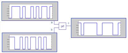
Binary logic describes the switching behavior of a binary (electronic) switch. Such a switch has two input signals ('a' and 'b') and one output signal ('c'), as shown in the next figure. A property of the input and output signals is that they all can assume one of two values in general given as '0' and '1'.
The shown switch executes the binary 'exclusive or' or 'NOT EQUAL' function. This means that the output c is '1' if 'a ≠ b'. Or if written for all possible combinations of 'a' and 'b':
- If 'a = 0' and 'b = 0' then 'c' is 0 (because 'a' and 'b' are equal).
- If 'a'= 0' and 'b = 1' then 'c' is 1 (because 'a' and 'b' are not equal).
- If 'a'= 1' and 'b = 0' then 'c' is 1 (because 'a' and 'b' are not equal).
- If 'a = 1' and 'b = 1' then 'c' is 0 (because 'a' and 'b' are equal).
These 4 combinations of 'a' and 'b' represent all possible combinations for 'a' and 'b' in binary logic. Usually the relation between possible input and output values are depicted in a matrix form called 'truth tables'. The following figure shows the truth table for the binary 'NOT EQUAL' function.
The possible values of the inputs 'a' and 'b' are the coordinates for the output 'c'. The input values of 'a' and 'b' are '0' or '1'. The possible values of the output 'c' are also '0' and '1'. There are 4 possible input combinations: (0,0), (0,1), (1,0) and (1,1). Each output can assume 2 different values. So there are 2 x 2 x 2 x 2= 16 possible different output combinations and consequently also 16 different binary 'truth tables'. These describe 16 different binary logic functions. The following figure shows all 16 possible binary truth tables.
For some functions (or truth tables) it does not matter if 'a' is 0 and 'b' is 1 or 'a' is 1 and 'b' is 0. Or the input state (0,1) is identical with (1,0). The truth tables are then symmetrical over their diagonal axis. These functions are called commutative. The addition of two numbers 'a' and 'b' is an example of a commutative function: a+b= b+a. If a function is not commutative it is called non-commutative. An example of a non-commutative function is a>b. If 'a' is greater than 'b' then 'b' cannot be greater than 'a'.
Commutativity in a logic function is more readily demonstrated in expressing it in an assignment expression. The 'exclusive or' or 'NOT EQUAL' function can be expressed as:
c → a ≠ b
which is equal to:
c → b ≠ a .
The right arrow is used as an assignment character to distinguish from the equal character '=' which is a logic function.
Binary signals
Binary signals are designated as being '0' or '1'. This does not mean that the corresponding signals are actually 0 Volt and 1 Volt. What it means is that the signal has two distinguishable and different levels and we just name them '0' and '1'.
The following figure shows a signal a=[0 1 1 1 0 1 0 0 1 0 1 0 1 1 0 1].
The shown signal consists of 16 individual binary elements or bits. Another binary signal is b=[1 1 0 0 1 0 1 0 1 1 0 1 0 1 0 0]. The following figure shows the signals 'a' and 'b' applied to the binary function 'NOT EQUAL' realizing the expression:
c → a ≠ b. It also shows the resulting signal 'c'.
2. Problems with logic states, values and meaning
Binary logic is the recognized foundation for computers and logic circuits. It is so well entrenched in our thinking and accepted as the fundament of logic that the binary concepts that were supposed to merely explain and clarify the application of binary logic now largely dictate our understanding of logic.
For instance 1 and 0 are 'known' to be equivalent to 'true' and 'false'. And the logic '1' is equivalent with the arithmetical '1', that is why computers can do calculations. This is not incorrect, but there are some qualifications to that statement:
1. electronic binary signal voltage levels are 'low' or 'high'
2. 'low' levels are called '0' and 'high' levels are called '1'
3. the truth table of the binary '≠' switch coincides with the modulo-2 addition function
4. the '≠' function is assumed to be identical with the modulo-2 addition
5. the logic '1' is assumed to be identical to the arithmetical '1' and the logical '0' is assumed to be identical to the arithmetical '0'.
There is no fundamental reason why we cannot make the '1' state equivalent to the arithmetical '2'. This seems far fetched. However in digital wireless communications the logic '0' is set as equivalent to the arithmetical '-1' to calculate correlation properties.
In general we consider '0' and '1' as fundamental properties of switching logic. By assigning these values to logic states we have given meaning or value to (what essentially are) meaningless logic states. This is a two-edged sword. It helps us work with binary logic, but it also limits our capability to look beyond binary logic. Mainly because concepts like 'true' and 'false' or 'on' and 'off' have no equivalent in multi-value logic.
Even more serious trouble arises around concepts like inversion of states or values. In binary logic the opposite of '1' is '0'. Or the opposite of 'true' is 'false'. It is reasonable to assume that if '0' is 'false' and '1' is true that '2' as a third state has to mean something like 'perhaps'. But 'perhaps' as we understand it is no state. And we also do not have an inversion for it.
States in reality are meaningless. They are just what they are: names or labels for something that is different from something else. Also there are limited ways to get from one state to another one by applying logic. To say that states are meaningless does not mean that they are useless. It just means that they do not have any inherent value or meaning. To clarify the concept of a 'meaningless' state the following figure shows the truth table for the binary '≠' function. However the binary logic states are now 'green' and 'red'. Another example is to use '3' and '5' as designated states.

These truth tables have little significance beyond describing some switching mechanism. When we can look at binary logic as 2-state switching with arbitrarily named states it becomes much easier to accept 3-state switching as ternary logic without worrying what these states may signify.
3.
Multi-value logic
Multi-value logic is defined as a non-binary logic and involves the switching
between more than 2 states. We will assume that multi-value logic devices
will be limited to 2 inputs/single output functions. A ternary or 3-value
logic function is one that has two inputs which can assume three states
(say 0, 1 and 2) and generates one output signal that can have one of
these three states.
Symbolically a ternary device 'ter' looks the same as a binary one with
two inputs and one output.
The truth table of a ternary device looks different from a binary one
as there is one more state to deal with. The following figure shows the
truth table of a ternary logic function.
This function is commutative (as it doesn't matter if we exchange the
'a' and 'b' inputs). It pretty much looks the same as binary logic, but
there are some major differences. Binary logic has 16 different functions.
Ternary logic has 3x3x3x3x3x3x3x3x3= 19,683 different functions of which
729 are commutative.
For illustrative purposes the following Visual Basic program may be used.
It executes a non-commutative ternary logic function. The inputs can be
changed and the program will generate the correct output states. The truth
table will identify the correct state. To make the distinction between
value and state the input and output signals are color coded.
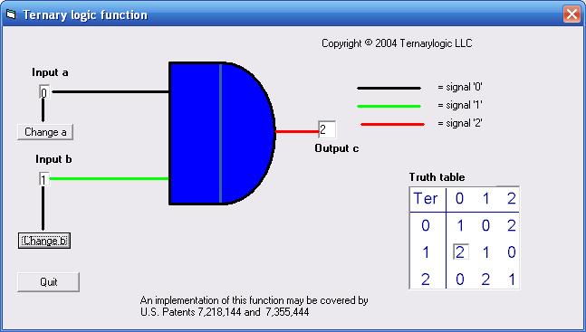
The VB program can be downloaded in ZIP form by clicking here or on the screenshot.
Ternary signals
Ternary input and output signals can assume one of three levels. Consequently they have more 'information content' than binary signals. The following figure shows the ternary signal a= [2 1 0 1 1 0 2 0 2 2 1 2 0 1 0 2].
The following figure shows the ternary input signals 'a' and 'b' and the ternary output signal 'c' of a ternary logic device executing ternary logic function 'ter'.
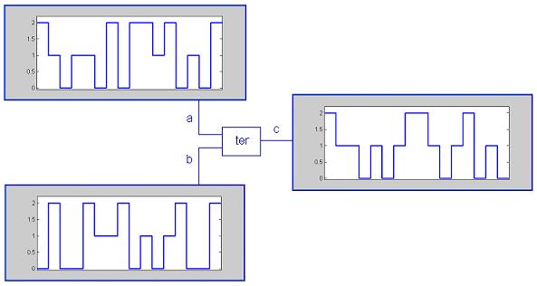
This demonstrates how to apply non-binary logic. Keep in mind that the values 0, 1 and 2 are assigned by us and are not inherent to ternary logic. They can for instance be -1, 0 and +1, which is useful in balancing the DC component of the signals, without changing the essence of the logic functions.
The same approach can be applied to other non-binary logics, such as 4-value logic. The number of possible 4-value logic functions is around 4 billion.
4. Multi-value logic inverters
It may seem that multi-value logic is similar to binary logic just with more states and functions. While this is in part true it would ignore fundamentally different properties of multi-value logic compared to binary logic. It is not the purpose of this web page to provide an in-depth analysis of multi-value logic. However one aspect that must be pointed out is the use of state (or value) inversion in multi-value logic.
In binary logic each of the two states '0' and '1' has one inversion. The inversion of '0' is '1' and the inversion of '1' is '0'. Each state has the other as its inversion. This is of course not possible in non-binary logic.
An arithmetical approach to inverters in an m-valued logic in the literature is provided by the formula:
x = (m-1) - y
In this formula y is the 'original' value and x is the 'inverted' value of y.
Much of the literature uses this approach and you will see in many articles that x = [ 2 1 0] is used as the standard ternary inverter of y = [0 1 2]. There are several unsatisfactory aspects to this definition, here are three of them:
a. logic states are being defined on the basis of assigned values
b. not every ternary state can be 'inverted' into another ternary state
c. this inverter is of limited use
State based ternary inverters
In ternary logic there are three states, which we named '0', '1' and '2'. The inversion of state '0' can be '1' or '2'. The most useful inversion is one that can be reversed. For instance the inversion of '0' can be '2' and the inversion of '2' can be '0'. That leaves '1' to have itself as an inversion. The inversion of the signal a=[0 1 2] would then be a'=[2 1 0]. And the inversion of a' is a''=[0 1 2].
Another ternary inversion is where '0' is inverted to '1', '1' is inverted to '2' and '2' is inverted to '0'. The ternary signal a=[0 1 2] has then as its inversion a'=[1 2 0]. The inversion of a' is a''=[2 0 1] and the inversion of a'' is a'''=[0 1 2].
The term inversion in this context is a bit problematic. We are all familiar with inversion as a concept in arithmetic and number theory. In number theory inversion is directly connected with the zero or "null" element. Its existence is one of the axioms for a Field in an Abelian Group under addition. That means that an element 'x' has as inversion an element '-x' such that in addition: (x) + (-x) = 0 .
Because we apply logic to execute arithmetical operations such as addition there is ample opportunity to mix and confuse concepts in logic and arithmetic. However in logic we can define a reversible inversion as a state transformation, with such properties that a state transformed at least 2 consecutive times by an inversion will reach its original state.
Ternary logic has 6 reversible inverters (including the identity). This offers an opportunity for executing certain operations that cannot be done in binary logic, especially related to scrambling of signals and generating of non-binary sequences with some very specific properties. These and other applications are subjects of pending patents with the US Patent and Trademark Office.
5. Binary and ternary ripple adders
Arithmetic and especially addition is often used as an example to demonstrate how binary logic can be "usefully" applied (ignoring the significance of the "control" capabilities of binary logic). This is where we have to provide meaning to states. Applying binary logic to adding two numbers in a base-2 counting system (or radix-2 addition) means that logic state '0' represents the number 0 and the logic state '1' represents the number 1. Adding in radix-2 now looks very much like adding in base 10, as we will apply the same rules:
1. create two numbers in base-2 notation
2. add the numbers base-2 or modulo-2
3. determine if the added numbers create a base-2 carry
4. create two numbers: the modulo-2 addition and the carry results
5. start again at item number 2 of this list and continue until no carry digits are left
This means that two different binary functions are needed: the modulo-2 addition which is the same as the binary 'NOT EQUAL' function. And the 'determine if carry is 1' function, which is the binary 'AND' function.
The same process can be applied to a base-3 or ternary adder. The following figure shows a screen shot of a ternary full adder applying ternary logic functions. The program also executes in parallel a binary adder, so you can compare the number of cycles to complete an addition. It also allows to compare the ripple effect of the carry in ternary and binary addition.
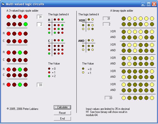
The VB program executing the adder functions in ternary and binary form can be downloaded in zipped format by clicking here or on the figure. Please note that only input values up to 35 are correctly displayed.
6. Multi-value signal processing and multi-value logic
In general multi-value logic or non-binary logic is positioned as a technology that can execute arithmetical functions faster and with less interconnect than binary logic. Further more non-binary data storage would require less physical space than binary data. This is especially important as we are starting to distinguish in the future the limitations of binary logic in silicon.
Even before we see the sunset of binary silicon technology we already are running into other capacity constraints, such as limitations of available bandwidth and spectrum in cable and wireless communications, data storage, processing of noisy signals, watermarking and other signal processing oriented requirements. The application of multi-value (non-binary) digital signals can provide considerable relief of capacity constraints. Applying multi-value logic to the processing of multi-value digital signals can also greatly improve the quality and the cost of multi-value digital signal processing.
Strangely enough multi-value digital signal processing can be done in binary logic, by processing the multi-value symbols as binary words. This principle, well documented but not generally known, is applied in for instance line coding for digital transmission. In the 1980s we saw the appearance of 4B3T codes. In this line-coding scheme a 4 bits binary word is translated into a 3 ternary elements ternary word. Even though the transmission takes place in ternary symbols, all processing such as scrambling and descrambling currently is done in binary logic. The great disadvantage of this approach is the requirement for word synchronization, coding overhead and maintaining a Running Digital Sum. Multi-value line-coding offers an immediate increased use of bandwidth and clearly is worth the cost of processing ternary symbols as binary words.
7. The gates, switches and physics
It is not uncommon to hear people assert that the limitations of MVL are caused by the lack of physical multi-value switches. There appears to be some truth to that. But contrary to popular belief we do not need some new exotic physical switching mechanism to realize ternary or multi-valued logic functions. There are sufficient known electronic mechanisms to build any required multi-valued logic functions by applying a limited number of gates.
Recently new technology has been invented (such as SUS-LOC) that allows for direct implementation of multi-value inverters in standard CMOS silicon. SUS-LOC was invented and patented by Dan Olson as USPTO Patent 6,133,754 . Olivier Sentieys and his group at the University of Rennes have applied this technology in designing a basic ternary Digital Signal Processor.
A search on the Web as well in patent databases such as the USPTO 's will provide a whole range of possible physical realizations of MVL switches.
8. The multi-valued latch
Anyone who has designed a logic circuit knows that at certain times sequential circuitry is required. These usually come in the shape of flip-flops or latches. The interesting part about latches is that they work because of the applied switching functions (such as NANDS), not because of the selected switching technology.
This raises then the question how MVL switching functions have to be selected and configured to realize an MVL latch. It turns out that the MVL latch is an extension of the binary latch. But it is a somewhat unexpected extension. Luckily one can actually create MVL memory element using fewer switching elements. These configurations can be viewed in one of my patent applications. The current or classic latch configuration is selected as example because it is in the same class as the binary latches.
The following figure shows a configuration of a 4-valued latch. It is comprised of 4 identical 4-valued switching devices 'latch4', configured in feed-back connection. The circuit has 4 inputs, In_1, In_2, In_3 and In_4. The output Out of the second device is used as the output of the complete Latch.
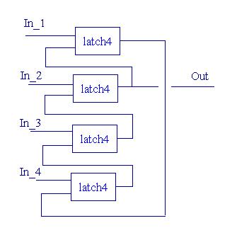
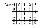
The truth table of the 4-valued device 'latch4' is provided in the following truth table.
The way this Latch works is as follows: inputs [In_1 In_2 In-3 In_4] can assume the following values [0 3 3 3]; [3 0 3 3]; [3 3 0 3]; [3 3 3 0] and [3 3 3 3].
The input [0 3 3 3] generates Out=0;
The input [3 0 3 3] generates Out=1;
The input [3 3 0 3] generates Out=2;
The input [3 3 3 0] generates Out=3;
The input [3 3 3 3] generates Out= previous Out;
Clearly this latch requires translation circuitry to transform a to be retained input value in a combination of 0 and 3s. The output of the second device is selected as system Out, because on this output a not inverted output is generated, as compared to the input. The input state [3 3 3 3] is the neutral state. That means when the inputs are switched to that state, the output generated by the previous input state is retained. The neutral state and the input states are identified using a switching model and selected because it allows for switching of just one input to neutral.
One can switch from [3 0 3 3] to [3 3 3 3] by just changing the state on one input. One may switch from [3 0 3 3] to for instance [3 3 3 0] without adverse effects. The output value Out will just change from 1 to 3 with some uncertain intermediate states. However the system will stabilize on the required end value.
It is possible to find switching functions that have stable outputs with a larger difference than 1 state between the inputs. Physically that means that several input values have to change at the same time. Failure to switch in an exactly synchronous manner to the neutral state may create unwanted stable intermediate states, and upset the 'latch' performance.
One can easily recognize the standard binary latch in this. In a way the result is somewhat disappointing because it requires an inordinate number of switching devices. Fortunately one can create much more compact two-function and even one-function MVL devices with feed-back to realize MVL memory elements.
Related to designing the MVL latches is a switching model that will be needed to find the appropriate MVL functions. It has been disclosed in one of my patent applications.
9. What can you do with it ?
Interesting stuff this MVL, but can you do something useful with it? Yes...One can for instance create multi-valued scramblers, descramblers, sequence generators and sequence detectors with the tools here provided. It is beyond the scope of this page to explain the intricacies of LFSRs. However a self-running Powerpoint presentation can be downloaded, that contains embedded VB examples applying MVL. You can download it by clicking here. If you don't have Powerpoint you can download a free viewer from here. Unfortunately the viewer does not activate the VBA macros. In order to run the actual VBA programs you will have to 'enable macros'.
The following screenshot shows one of the actual programs. It shows a 4-valued sequence generators and the modified 4-valued descrambler to create the detector, including the truth tables. It also shows how the LFSR is 'flushed'.
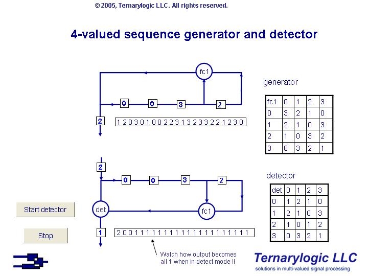
The file is zipped. In order to run the actual scramblers and descramblers you should unzip it and enable the macros.
10. The strangeness factor
There is a strangeness associated with MVL. It seems that binary logic
is much more natural and intuitive. It is quite common to show '0's and
'1's in TV commercials, or advertising related to Internet applications
or computers. It appeals directly to our intuitive recognition of current
and advanced technology.
Binary logic (or logic for that matter) is NOT a law of nature. The reason why binary logic seems more natural is because we have been more exposed to it. The feeling of strangeness in MVL disappears once you start working with it. There is no inherent conflict with binary logic once a familiarity with the concepts has been established.
There are much "stranger" and very intriguing (non-classical) logics out there. From that perspective MVL is more like an extension of binary logic and very conventional, though broader in possibilities.
In fact when MVL will be applied on a larger scale we predict that the MV will be dropped from the MVL and the subject will be known as Logic.
11. An analogy
To give an example of things that are possible in ternary logic but not in binary logic we will provide the following analogy:
We can compare binary logic with driving in Manhattan, and are only allowed to drive straight or turn right. Under those conditions there are Targets we will not be able to reach. We will be able to reach those Targets if we are also allowed to turn left. Check the correctness of this in the following figure.
MVL allows us to do things that are not possible in
binary logic and we can achieve them in many more ways than in binary.
MVL functions can be very useful in applications such as line-coding,
data-scrambling, sequence generation for wireless applications, arithmetical
engines, and for what probably would be called digital control and MVL
combinational applications. The details of these applications are beyond
the scope of this introductory web site. However these applications have
been developed, simulated in software, tested and validated.
12. Patents
and Patent Applications
Is this stuff useful, or is it merely an exercise for the brain? That
is a question we often hear after explaining the concepts of MVL. But
yes, it really works. How one can realize MVL circuits and what applications
one may want to realize in MVL is the subject of a series of Patent Applications.
These patent applications have already been published by the US Patent
and Trademark Office and can be downloaded in PDF file by clicking on
the title. The patent applications are of a set of over 35 inventions.
Some of the inventions are pure multi-valued. Others, such as the one
on convolutional codes, also deal with binary applications.
Please take a look at www.ternarylogic.com/portfolio.pdf for an overview of the portfolio.
The 9x9 Sudoku matrix is a set of 9 orthogonal reversible 9-valued inverters. Such an inverter is also a sequence of 9 different symbols put in a pseudo-random fashion in the sequence. One can generate such a sequence from a maximum length sequence of 3-valued symbols generated by a word method using 9 overlapping words of 2 ternary symbols. Such a sequence cannot be generated by an LFSR. By replacing each word with its decimal equivalent one then obtains the sequence of 9 different symbols. This sequence can be interpreted as a transposition rule. By performing the transposition rule upon itself and upon the transposition results one can obtain 9 different orthogonal sequences. One can apply this method using a ternary m-sequence of 26 symbols, and thus generating a 26x26 Sudoku matrix of 26 orthogonal sequences of 26 different symbols.
14.
Scramblers and Descramblers
An Escher-esque Linear Feedback
Shift Register?
They are called "impossible" figures, which show drawings that appear to be physically impossible.
The Escher drawings appear to be more impossible because of the depiction of a pseudo-physical environment.
Feedback in
some cases appear to represent an impossible situation. The following
diagram shows a Linear Feedback Shift Register scrambler with a corresponding
descrambler. (taken from US Patent Application Publication Ser. No. 20090138535.)
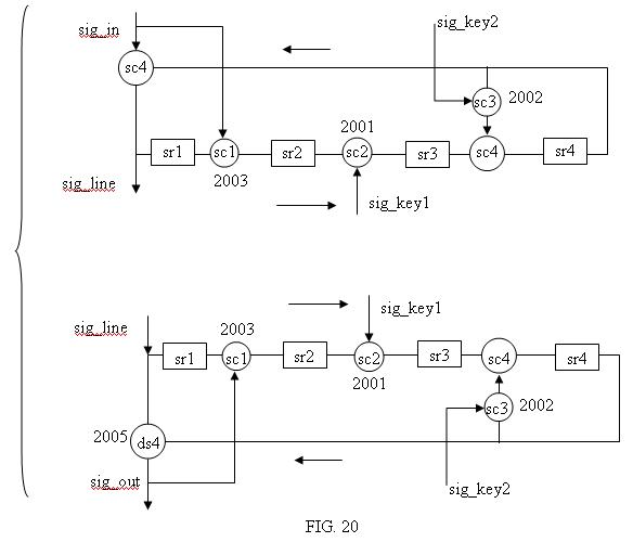
It shows in the bottom figure that a correctly descrambled symbol is required
on the output of 'ds4' to generate correctly descrambled symbols in 'sig_out'.
Yes, that is correct: you need to correctly descramble symbols to correctly descramble. An impossible figure?
Not at all. It actually works beautifully, as is demonstrated in the following Matlab/Freemat program. The delay formed by the shift register makes this work.
The LFSR (which may be binary or non-binary) in this case is in Galois configuration and is not self-synchronizing. This requires that the initial state of the shift register in the descrambler is identical to the initial state of the shift register of the scrambler.
In the following
implementation only sc1, sc3, sc4 and ds4 are considered.
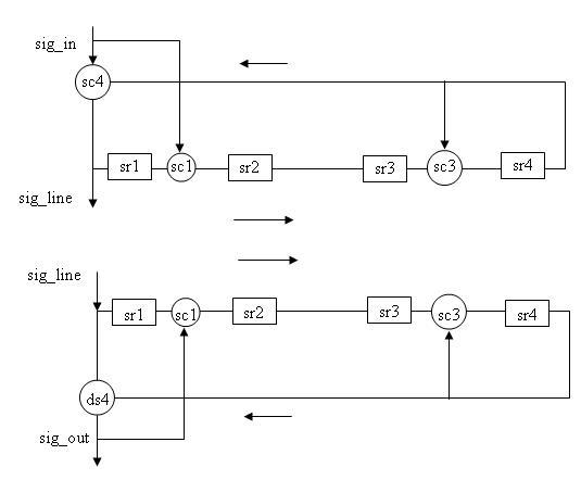
A binary implementation of the above
scrambler/descrambler as '.m' files which can be run in Matlab/Freemat
with a fixed sequence 'sin1' is provided here.
To Run:
a) Open the zip files and store '.m' files in a directory which is in
the path of Matlab or Freemat.
b) for the binary case first run the scrambler 'novscramlfsrbingala' to
scramble and
'novdscramlfsrbingala' to descramble. Modify programs with Freemat/Matlab
editor for instance in initial state of the shift register.
c) compare input sequence 'sin1' with scrambled sequence 'outb' and descrambled
sequence 'res1'.
d) for the
4-state case first run the scrambler 'novscramlfsr4gala' to scramble and
'novdscramlfsr4gala' to descramble. Modify programs with Freemat/Matlab
editor for instance in initial state of the shift register.
e) compare input sequence 'sin4' with scrambled sequence 'out4' and descrambled
sequence 'res4'.
Public/Private Mode
Another feature of the above scrambler/descrambler is its public/private mode.
In the binary case the function sc4 can be a XOR function whereon an all zero ([0 0 0 0 ...0]) sig_key sequence is provided. This makes sc4 transparent as the output of sc4 provides the same symbols as it received from sc1. For instance it makes the inclusion of sc4 in the descrambler unnecessary.
By modifying sig_key to for instance a pseudo-noise sequence, the descrambler, if it did not apply sc4, is no longer able to correctly descramble the scrambled sequence.
The same approach can be applied in non-binary or n-state scramblers/descramblers, for instance by using as sc4 a function represented by a standard addition over GF(n).
Examples
Feel free
to play with the attached programs for educational purposes only. Please
keep in mind that a patent is pending on this subject.
15.
Contact
©2013, Peter Lablans. All rights reserved.
You may use the content of this site for private use only. If you use
any of this site's content you have to acknowledge it as: Source:
"N-state switching " at "www.multivaluedlogic.com", author Peter Lablans.
No further permission for private use only is required. Commercial use
of all or any of the aspects of this site is strictly prohibited. If you
did not invent it and it is protected IP it is clearly not yours and you
should seek permission to use it. For educational and commercial use please
contact admin at ternarylogic dot com.
Further information on Ternarylogic LLC and its portfolio can be found
at www.ternarylogic.com
[TOP]